WELCOME
Dear User,
Thank you for choosing Portman S-TRIBE™ – the original product with a registered design.
We are proud to deliver you the highest quality, greatest design and real passion with our product.
Each fixture in the Portman portfolio is different, yet all of them ensure you the best performance to support your creativity.
FOR YOUR SAFETY, PLEASE READ THIS USER MANUAL CAREFULLY BEFORE YOUR INITIAL START-UP!
Please remember:
- any updates on this document,
- current products’ libraries,
- current products’ firmware,
- RMA procedure
can be found on our webpage in the support area:
WARNING! This product is for professional use only! It is not for household use.
This product presents a risk of lethal or severe injury due to heat, electric shock, fire or falls.
Intense and flashing light could trigger epileptic seizures. Read this manual before your
initial start-up and follow the safety information in this manual and engraved on the fixture.
Every person involved in the installation, service and maintenance of this device must be
qualified and have experience in working with stage lighting fixtures.
Before your initial start-up, please make sure that there is no damage caused by transportation.
Should there be any, consult your dealer and do not use the device.
Please consider that damages caused by manual modifications to the device are not subject to warranty.
CAUTION! Keep this device away from rain and moisture!
CAUTION! Be careful with your operations! With a dangerous voltage you can
suffer an electrical shock when touching the fixture and wires!
CAUTION! When in operation the fixture’s surface becomes hot. Allow the device
to cool down for approximately 30 minutes before any maintenance or service.
Keep a minimum 0,2-meter distance from flammable materials to the fixture.
CAUTION! Avoid looking directly into the light source (meant especially for epileptics)!
CAUTION! Unplug the mains lead before opening the housing.
Protection against electrical shock
• Disconnect the fixture from AC power when not in use.
• Disconnect the fixture from AC power before any maintenance or service.
• Do not remove the rear cover. There are no user-serviceable parts inside.
• Always ground the fixture electrically.
• Use only the wires attached to the kit. If the power cable shows any sign of damage do not use it!
• Use only a source of AC power that complies with local building and electrical codes and has both overload and ground-fault protection.
• Do not expose the fixture to rain or moisture.
Protection against burns and fire
• Never operate when the fixture is damaged or some part is missing.
• Do not touch the surface when the fixture is in operation. The exterior of the fixture can reach temperatures up to 70°C (158°F). Allow the fixture to cool for approximately 30 minutes before any maintenance or service.
• Keep all combustible and flammable materials (for example fabric, wood, paper) at a distance of at least 20 centimetres away from the fixture. Do not cover the fixture when in operation and when it is hot.
• Do not modify the fixture.
• Do not operate the fixture if the ambient air temperature exceeds 45°C (113°F).
• Do not operate the fixture after an extreme change in the surrounding environment temperature. Allow the fixture to acclimate for at least an hour before operating.
Protection against falls
• Use only professional tripods and clamps to mount the fixture. Ensure, that the clamp or tripod is designed to withstand the weight of the fixture.
• Ensure that the structure intended for installation can hold at least 10 times the weight of all installed devices.
• Ensure that all fixtures are attached correctly to the structure and use an approved means of secondary attachment such as a safety cable.
• Block access below the work area whenever installing or removing the fixture.
Protection against eyesight damage and epileptic seizure
• Do not stare directly into the light sources. Never look at an exposed light source while it is lit.
• Provide advance notice that a flashlight is in use.
• Avoid long cycles of rapid flashing light.
• Always use safety glasses to protect your eyes when opening the front cover.
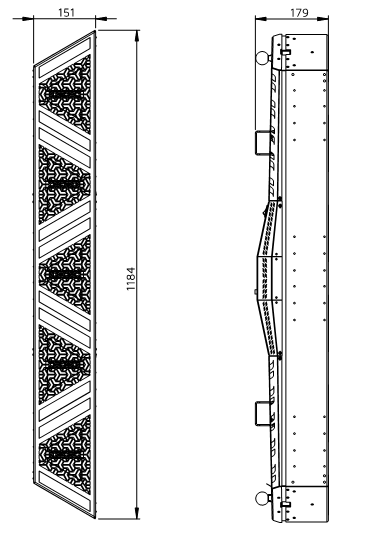
TECHNICAL SPECIFICATION
| dimensions |
1184 x 151 x 179mm |
| (46.61 x 5.94 x 7.05in) |
| weight (fixture
only) |
8 kg |
| (17,64 lbs) |
| input voltage |
100-240V 50Hz/60Hz |
| power consumption |
max 280W |
| light source |
portman haloLED™ |
RGBW GLOW |
| power |
5 x 40W |
10 x 8W |
| luminous flux |
5500lm |
1200lm |
| colour temperature |
1600K – 3200K |
R G B
+ White 6000K |
| CRI |
>80 |
| beam angle |
94o |
| DMX channels |
12, 17, 32, 57, 52, 97 |
| DMX modes |
6 |
| connectors |
2 x 5-PIN DMX |
| 1 x
EtherCON |
| 1 x AC
powerCON TRUE1 (inlet and outlet) |
| 1 x SMA
(WDMX antenna) *optional |
| other features |
built-in drivers |
| Portman
Colour Feedback System™ |
| Auto
Orientation™ |
| built-in
macros |
| WDMX
module optional |
| Appliance class |
Class I |
|
| IP rating |
IP20 |
| declarations of conformity |
CE |
UKCA |
|
PRODUCT OVERVIEW
Dimension
Kit content (what’s in the box)
• 1x S-TRIBE™ • 1x AC power wire 2m • 1x User Manual • 1x base • 1x QJS™ hanging adapter • 1x QJS™ spigot
|
|
Optional accessories (not included)
• W-DMX module
• flight case
S-TRIBE™ is fully compatible with the AMULET™ fixture and its accessories (base, hanging adaptor, spigot).
PREPARATION FOR USE
AC power connection
Luminaire must be powered with 100-240V and 50/60Hz. This fixture will automatically detect the alternating current frequency. To turn on the fixture, simply plug in the powerCON TRUE1 and set the power switch to “ON”. Use only high quality 3 x 2.5 mm2 or larger mains power cords. Inspect all the power feed cables for damages before use. Make sure to always connect the fixtures to a protected circuit with an appropriate electrical ground. Never connect the fixture to a dimmer plug, even if it supplies proper current.
Only qualified electricians following all known electrical regulations can install the fixtures.
Luminaire comes with a power input cord terminated with powerCON TRUE1 on one end and tube connectors on the other end. Follow the rules from the table below to assemble the power plug to the wire:
| Connection |
EU wires |
US wires |
| Live |
L |
Brown |
Black |
| Neutral |
N |
Blue |
White |
| Earth |
PE |
Green/Yellow |
Green or Green/Yellow
|
CAUTION! Do not use the power cord without a plug attached!
CAUTION! Always double-check the wire with a plug attached before use!
REMEMBER! Only a qualified person can change or install the plug!
Installation
Before mounting the fixture, read and follow all safety recommendations indicated in the Safety Information.
The luminaire may be installed on a tripod, a clamp or a floor base. The fixture has two 13 mm (0.512 in) holes for a rigging clamp or screw. Before rigging operations make sure that the structure onto which you are mounting the fixtures can withstand the weight of all of the fixtures. Check if there is enough room for ventilation, configuration and maintenance in the location where you want to place the fixture. You must secure every hanged fixture with an appropriate safety wire. Make sure there are no people under the work area when hanging fixtures.
To hang the fixture on a clamp under the truss you have to install the hanging adapter using Quick Joint System™. Always double-check if the hanging adapter is attached properly to the fixture and the spigot is locked. The back hanging brackets and the hanging adapter have 13 mm (0,.512 in) holes for the spigot or rigging clamp. Before rigging operations make sure, that the structure onto which you are mounting the fixtures can withstand the weight of all of the fixtures. Check if there is enough room for ventilation, configuration and maintenance in the location where you want to place the fixture. You must secure every hanged fixture with the appropriate safety wire. Make sure there are no people under the work area when hanging fixtures. You can aim the fixture to any position that you want except towards the rigging structure. Remember not to let the power and DMX wires touch the surface of the fixture. Always keep a safe distance from the closest object.
REMEMBER! Always secure the hung fixture with safety wire!
CAUTION! Incorrect installation may result in the device falling and may damage it or cause damage to other objects!
CAUTION! Always use only original spigots and cotters to install or hang the fixture. Never use other brands’ spigots.
REMEMBER! Never use more than two units on base or on the hanging clamp without additional safety support
Quick Joint System™ (QJS)
To connect S-TRIBE together you can use the Quick Joint System™. The system was also designed to connect accessories to the fixture. The S-TRIBE comes with the QJS spigot and with the QJS adapter. The heart of the system is the QJS spigot. To make a connection you can just slide it in the QJS socket and secure it using the safety spring. To establish a safety connection slide the QJS™ spigot into the QJS™ socket. After you place the spigot in the socket please make sure that the locking pin is fully hidden in the sleeve. You should not be able to see the locking pin when the spigot is properly mounted. Always double check if the locking pin is fully hidden in its sleeve. CAUTION! Never use the fixture if the locking pin is not locked properly.
After placing the QJS™ spigot in the QJS™ socket properly, secure the connection by rotating the safety spring and the ball attached to the locking pin. Simply pull the securing spring towards the ball and rotate it to the locking position.
Repeat the same steps if you want to
connect another fixture or an accessory to the S-TRIBE. If you want to release
the QJS™ spigot, unlock the safety spring by pulling it towards the ball and
rotating it to the release position. After you set the safety spring in the
right position pull the ball with locking pin and slide the spigot out of the
QJS™ socket.
Operation modes
The luminaire can work in three operation
modes: DMX, MASTER and SLAVE. DMX mode is designed to work with DMX consoles.
MASTER mode is designed to operate the fixture manually, without an external
controlling signal. In the MASTER mode, the fixture sends a controlling signal
on the DMX output socket. The signal can control other units in SLAVE mode.
Please consider that unit in MASTER mode connected to a regular DMX chain can
corrupt DMX signal quality. The SLAVE mode allows you to control the fixture
with the control signal sent from a unit in MASTER mode. However, the DMX
signal has got the highest priority and the fixture always reacts to the
connected DMX signal regardless of the operating mode.
| Event |
Operating Mode |
| DMX |
Master |
Slave |
| DMX wire connected |
Reacts to DMX |
Reacts to DMX |
Reacts to DMX |
| WDMX connected |
Reacts to WDMX |
Stays in Master
Mode |
Receives control
signal from Master unit |
| DMX disconnected |
Keeps last DMX
frame |
Gets back to the
last Macro or Manual setting |
Receives control
signal from Master unit |
| After power reset |
All values
default |
Gets back to the
last Macro or Manual setting |
Receives control
signal from Master unit |
There are three ways to operate the fixture in the DMX OPERATING MODE. You can use DMX input signal, onboard manual control or WDMX input signal to control the fixture(if the WDMX card is installed). You can link the fixture to a DMX controller using a 5 pin DMX wire, or Wireless Solution Sweden hardware (if the WDMX card is installed). You can control each channel individually whether with a DMX controller or a manual control build in the fixture. The fixture has 6 DMX personalities and it supports RDM. In DMX mode fixture will not remember the manual settings after a reset is performed.
To remember the manual settings you have to use MASTER mode. You can set any lighting scene using the manual control section in the fixture’s menu or play build-in macros. The fixture always switches to DMX when a DMX wire is connected. After disconnecting DMX in MASTER mode the fixture always goes back to the last macro/manual setting. After a power reset the unit remembers the last manual/macro settings. If you are going to control the fixture by onboard manual control it is recommended to use MASTER OPERATING MODE.
RDM
RDM (Remote Device Management) is an enhancement of the DMX 512 protocol and allows bi-directional communication between DMX consoles and fixtures. It works simultaneously with DMX 512 and on the same lines and wires. RDM is not affecting non-RDM devices in a line however, non-RDM devices can disrupt communication with the console. RDM allows you to change the fixture’s options (such as DMX address) without even touching neither ladder or fixture’s buttons. The fixture fully supports the RDM standards.
Manual operation
The fixture works in manual operation when it’s not receiving DMX signal whether wired or wireless. You can adjust the brightness of all LED sources at once from the main screen, or you can control each source individually from the “CONTROL ME MANUALLY” option in the menu (refer to the “Menu” chapter to learn how to manually control channels). To enter the menu simply press “ENTER”.
DMX 512
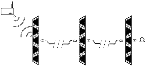
The fixture automatically switches into DMX mode after receiving DMX data. To learn how to change the DMX address or signal source (wired or wireless) refer to the “Menu” chapter. When the fixture works in the wired DMX mode You can daisy chain fixtures using 5 pin DMX wires. When daisy-chaining remember, that you can connect up to 32 devices per DMX 512 universe. Always terminate the DMX 512 line. Put the 120 Ω terminator into the last device’s DMX OUT XLR socket. When the fixture is being operated in the
wireless mode (only when the WDMX card is installed) it is receiving DMX 512
signal from Wireless Solution Sweden transmitters and can send the signal
throughout the 5-pin DMX OUT XLR socket. You can put the fixture with the WDMX
card installed as the first fixture in a line and use it as a WDMX receiver.
The fixture supports a bi-directional WDMX TRX module. It means, that the
fixture supports RDM in wireless mode too. To link fixture with the WDMX
transmitter first use the “UNPAIR ALL WDMX DEVICES” option from the menu, then
turn the scanning mode on the transmitter. The transmitter will link with all
unlinked devices. For more detailed information please refer to your
transmitter’s user manual.
Art-Net
Art-Net is a data distribution protocol
created and copyrighted by Artistic Licence Holdings Ltd that allows to
transport DMX and RDM over an ethernet network. Art-Net is capable of
containing up to 32 768 DMX Universes. The S-TRIBE has an ethernet card built in
and it supports the Art-Net protocol. To run the fixture using Art-Net you have
to make a configuration of ethernet settings in the fixture as well as in the
console. To make it possible to work with Art-Net the console and the fixture
has to be in the same network. It is highly recommended to use 2.0.0.0/8 or
10.0.0.0/8 network. It is also suggested not to use DHCP options in the Art-Net
network. The S-TRIBE as a network device has its own unique MAC address which
cannot be modified. You can modify the IP address and the IP subnet mask. When configuring the network always remember
that each unit in the network must have unique IP address. After configuring
the Ethernet settings properly, you should set up the parameters of the Art-Net
network. You should set up the proper Art-Net universe, subnet and net. Because
Art-Net is a container of many DMX lines, you still have to set the proper DMX
address. For example if your console has an IP address 10.0.0.100/8 and you
patched the S-TRIBE at 4th DMX universe at address 53, you can set the Network
parameters in S-TRIBE as follows: IP address 10.0.0.101/8, Art-Net universe: 4,
Art-Net subnet: 0, Art-Net net: 0, DMX address: 53 (in this case you can output
the 4th DMX universe from the S-TRIBE DMX OUT XLR connector). Please refer to
the “Menu” chapter to learn more about Ethernet and Art-Net settings. The S-TRIBE can work as an Art-Net node which means that you can input Art-Net to a
fixture and output one full DMX universe on the DMX output XLR connector.
Auto Orientation™
To build a line using the luminaire you have to put
one unit in ‘regular’ position and the other unit in ‘upside down’ position. I
would be annoying to always take care about the right DMX channel order. With the
fixture you don’t have to care about its orientation any more. The Auto
Orientation™ detects where the top of the fixture is and sets the first DMX
channel regarding the gravity, not fixture position. Building and programming a
line of LED strips were never so easy before. Auto Orientation™ flips the DMX
channel order as well as the screen. In some cases you want to have a specific
channel order not related to the logical position of the fixture. You can set
the orientation manually in the menu then. The easiest way of recognizing where
is the first DMX channel is to look at the OLED screen in the back of the
device. The first channel is pointed by the top of the characters orientation
on the screen.
Navigation buttons are located under the LCD on the back panel. To enter the menu press the “Enter” button. To navigate the menu use the “+” and “-“ buttons. To exit the menu from any level press “ESC”. For confirming simply push the enter button.
Portman Colour Feedback System (CFS)™
Luminaire is equipped with Portman Colour Feedback System™. The navigation buttons under the OLED screen are highlighted with RGB LEDs. The Portman CFS allows you to check the fixture status without even touching the display or buttons. There are few possibilities:
| Button colour |
Fixture state |
| White |
Fixture receives DMX or
WDMX signal |
| Red flashing |
The fixture is in DMX
operating mode, but there is no DMX nor WDMX signal detected |
| Green |
The fixture is in MASTER
operating mode and there is no DMX signal detected |
| Blue flashing |
The fixture is in SLAVE
mode and there is no DMX nor MASTER signal detected |
| Blue |
The fixture is in SLAVE
mode and there is MASTER signal detected. There is no DMX signal. |
Portman Colour Feedback System™ works also when you operate the menu. When you navigate through the menu the buttons change their colours. In the first level of the menu, the buttons are blue, the second level of the menu is cyan. When you start editing a parameter in the menu the buttons turn red. Remember that any changes will not be saved until you confirm them with the “ENTER” button. The changes are stored only after you see the “You made it!” confirmation screen.
| Main section |
Level 1 |
Level 2 |
Level 3 |
Description |
| MY DMX ADDRESS: |
DMX ADDRESS |
|
|
Sets up the DMX
start address |
| MY PERSONAL SETTINGS |
DMX MODE |
SUPER SIMPLE |
|
Sets up the DMX mode. Refer to DMX chart for DMX
channels order. |
| |
|
SIMPLE |
|
|
| |
|
STANDARD |
|
|
| |
|
STANDARD FINE |
|
|
| |
|
PIXEL |
|
|
| |
|
PIXEL FINE |
|
|
| |
DMX INPUT |
WIRED |
|
Changes the DMX
input to wired (default). In this mode, the fixture is receiving a DMX signal
from the DMX IN 5 pin XLR socket. |
| |
|
WIRELESS |
|
Changes the DMX
input to wireless. This mode works only when the WDMX card is installed.
Fixture is receiving DMX data from the WDMX card. |
| |
OPERATING MODE |
DMX |
|
Changes the fixture’s operating mode. Refer to the
Operation Modes chapter for more info. DMX is default |
| |
|
MASTER |
|
|
| |
|
SLAVE |
|
|
| |
DIMM CURVE |
LINEAR |
|
Changes dimming curve of filaments. Halogen mode is
emulating the behavior of halogen using also glow sources. Logarithmic is the default. |
| |
|
LOGARITHMIC |
|
|
| |
FLICKER MODE |
MODE 1 (2.4kHz) |
|
Changes the frequency of the LED driving signals. |
| |
|
MODE 2 (3.2kHz) |
|
|
| |
|
MODE 3 (4.7kHz) |
|
|
| |
ORIENTATION |
UP |
|
Sets up the pixel order relation. Auto mode
discovers the orientation of the fixture automatically and sets the first
pixel of the fixture on the top. Please refer to Orientation chapter for more
info |
| |
|
DOWN |
|
|
| |
|
AUTO |
|
|
| |
DISPLAY AND BUTTONS |
DP BRIGHTNESS |
|
Changes the parameters of display and buttons
highlight. |
| |
|
DISPLAY OFF TIME |
|
|
| |
|
WELCOME SCREEN |
|
|
| |
|
NO DMX BTN FLASH |
|
|
| |
RESET ALL TO DEFAULT |
|
|
Resets all the options to default values. |
| ARTNET MAGIC |
ARTNET
is |
ENABLED |
|
Enables
or disables the Art-Net |
| |
|
DISABLED |
|
|
| |
MY IP ADDRESS |
XXX.XXX.XXX.XXX |
|
Sets up the IPv4 address of the fixture. The
address contains a series of four parts ranging from 0 to 255. To set the
value of the part use UP and DOWN buttons. To go to another part press ENTER
button. To get back to previous part press ESC button. To store the setting go through all 4 parts
and press ENTER again. |
| |
IP SUBNET MASK |
XXX.XXX.X.XXX |
|
Sets the subnet mask of the network. The
subnet mask consist of four parts. Each part can be set to 0 or 255. To set
the value of the part use UP and DOWN buttons. To go to another part press
ENTER button. To get back to previous part press ESC button. To store the setting go through all 4 parts
and press ENTER again. |
| |
ARTNET UNIVERSE |
0 - 255 |
|
Sets up the universe that the fixture is
patched on. The fixture will read data only from the universe set here. |
| |
ARTNET SUBNET |
0 - 255 |
|
Sets up the Art-Net subnet. |
| |
ARTNET NET |
0 - 128 |
|
Sets up the Art-Net net. |
| WANNA GO WIRELESS? |
UNPAIR ALL WDMX
DEVICES |
UNPAIRING MODE |
|
Unpairs all
connected WDMX transmitters |
| |
WDMX MODE |
G3 |
|
Switches between WDMX modes |
| |
|
G4 |
|
|
| |
|
G5 |
|
|
| |
WDMX INFO |
SIGNAL STRENGTH |
|
Shows WDMX card info. |
| |
|
LINK STATUS |
|
|
| |
|
RDM STATUS |
|
|
| |
|
DMX DATA STATUS |
|
|
| INFO ABOUT MYSELF |
WHO MADE ME |
|
|
Shows the name of
the fixture’s manufacturer. |
| |
MY NAME IS |
|
|
Shows the fixture’s
name given by the manufacturer. |
| |
YOU CALL ME |
|
|
Shows the fixture’s
name given by the user. |
| |
MY ID IS |
|
|
Shows the fixture’s
RDM unique ID number. |
| |
MY VERSION IS |
|
|
Shows actual
firmware version |
| |
I WORKED HARD FOR |
|
|
It Shows time the
fixture has been turned on |
| CONTROL ME MANUALLY |
MAIN SOURCES |
INTENSITY |
0 – 100% BRIGHTNESS |
Sets all main sources dimmer value |
| |
|
STROBE |
0 - 100% STROBE |
Sets all main
sources strobe value |
| |
GLOW |
INTENSITY |
0 – 100% BRIGHTNESS |
Sets glow all pixels dimmer value |
| |
|
RED |
0 – 100% RED |
Sets glow red value |
| |
|
GREEN |
0 – 100% GREEN |
Sets glow green
value |
| |
|
BLUE |
0 – 100% BLUE |
Glow blue value |
| |
|
WHITE |
0 – 100% WHITE |
Glow white value |
| |
MACRO |
MACRO |
MACRO NUMBER SELECT |
Selects macro |
| |
|
MACRO SPEED |
MACRO SPEED |
Sets the macro speed |
| |
|
MACRO INTENSITY |
0 – 100% BRIGHTNESS |
Sets macro intensity value |
Thank you for buying
original products!
By buying original products you buy the real
quality but also support creativity and
progress in the industry.
Any problem and/or question according to fixtures
– contact us following these steps:
1. Send a message here:
support@portmanlights.com
Remember to add these important details:
[Serial number of the fixture]
[Issue description, videos, pictures]
2. Continue using a ticket number
You will receive
an automatic ticket number. Our Support team has up to 48h to start resolving
the issue. You may be asked for more details by our support team or by a
distributor. Always use your ticket number for quicker resolution of the case.
© 2016-2024 Portman Lights Sp. z o. o. All rights reserved.
The information and specifications are subject to change without notice.
Portman Lights Sp. z o. o. disclaims liability for any injury, damage, direct or indirect loss,
consequential or economic loss or any other loss occasioned by the use of,
inability to use or reliance on the information contained in this user manual